092724 3rd Annual GEO-CT Conference
 This conference is sponsored by the CT Valley Chapter of the ASCE Geo-Institute.
Conference Attendee Evaluation Survey
Conference Program and Exhibitor Layout 
Thank you to our sponsors for making this Conference possible!
Bedrock Sponsors
![]()
Breakfast Sponsor 
Friday Reception Sponsor 
Foundation Sponsors:


Concrete Sponsors: 

The Fall 2024 GEO-CT conference will be held on September 27 at the Sheraton Hartford South in Rocky Hill, CT. Several New York State PDHs will be offered at this event. Please check back here or visit www.geo-ct.org for more information about this conference.


Rigid Inclusions: A Spectrum of Applicability
Rigid Inclusions (RIs), which are columns typically made of concrete or mortar, have been used to reduce settlement and increase bearing capacity by many geotechnical engineers, contractors, developers, and owners over the last 30 years. Over that time, the common practice has gone from using RIs as settlement mitigation elements on sites where stone columns or another type of ground improvement wasn’t sufficient to often being used in applications similar to piles. While the industry understands that RIs can be used for a wide variety of projects and soil conditions, engineers are not often clear of the implications of the project conditions on the design of the RIs. Based on the premise that there is no one-size-fits-all design, this presentation will highlight the wide variety of conditions (the spectrum) that RIs can be applied to and the associated considerations that come with a project’s place on the spectrum. It will address the importance of not requiring overly prescriptive design methods that limit the optimization and benefit that the RI solution can offer and may discounts the advancements that RI technology offers to our industry.
Interpretation and Evaluation of Thermal Integrity Profiling Measurements
Thermal Integrity Profiling (TIP) is a non-destructive method used to evaluate drilled deep foundation integrity. This integrity testing method is specified more frequently, and is becoming an industry standard in the transportation and private construction sectors. This testing method utilizes heat generated during the concrete/grout curing process to assess deep foundation integrity over the evaluated length. With compilation of the measured temperature versus time and installation records, a model of the Effective Average Radius versus measurement depth is generated. The generated effective shaft model is highly dependent on specific construction details, subjective modeling parameters, and proper interpretation of concrete/soil heat dissipation characteristics.
Key components of the TIP analysis include both qualitative and quantitative assessments. Qualitatively, variations or sharp reductions in temperature profiles may indicate potential anomalous regions. Quantitatively, a correlation is established between measured temperatures and estimated Effective Radii for subsequent integrity evaluation. Best practices in processing the TIP measurements are presented, including selecting the optimal time for analysis, normalizing the thermal profile, and proper interpretation of potential anomalous regions. Recommendations for implementing mitigation efforts and interpretation of the TIP results are presented.
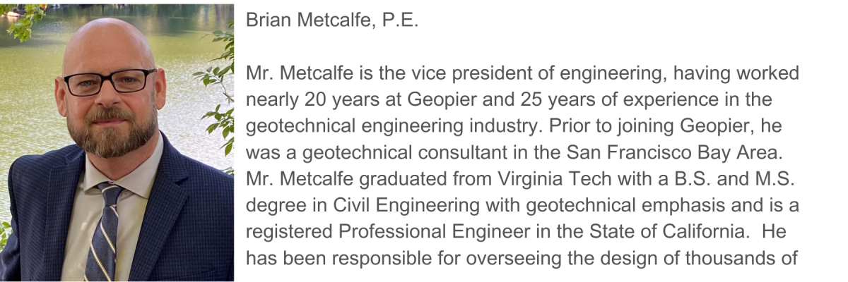

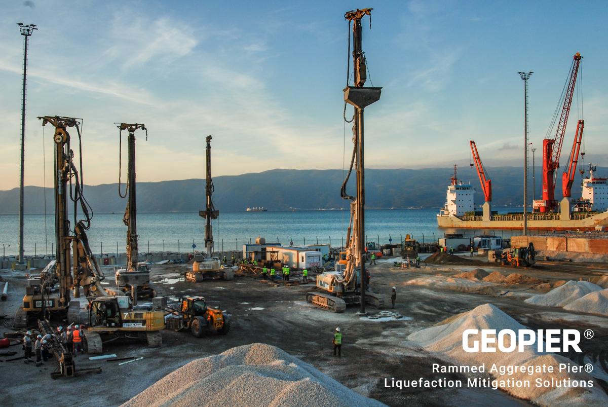
Rammed Aggregate Pier® Elements for Liquefaction Abatement
Seismic design loads across the United States have increasingly become a significant design consideration in the safe performance of structures. The impacts of changes in building codes on New England construction results in many sites that are now susceptible to unacceptable seismic deformations resulting from liquefaction induced settlements as a result of increase design ground motions.
Liquefaction induced settlements can be mitigated by structural design by transferring building loads through the potentially liquefiable soil, stiffening foundations, or other structural mitigation. In lieu of structural mitigation; which can be costly, including the design of piles to resist lateral loads, ground improvement can be considered to mitigate liquefaction induced settlement to tolerable magnitudes.
This session will present Rammed Aggregate Pier® RAP methods as an effective way to mitigate liquefaction induced settlements. RAP elements have been used extensively to control liquefaction induced settlements worldwide. The presentation will discuss the mechanisms that RAP elements mitigate liquefaction including case histories on the results of a Geopier® supported embankment that withstood a Magnitude 7.8 earthquake in Ecuador and other full scale testing programs and research that validates the Geopier design approaches.

Managing Unstable Road Slopes Through Data-Driven Risk Assessment
Roadway slopes and embankments are two types of geotechnical assets defined by the Transportation Research Board and integral parts of asset management program initiatives. By implementing risk-based concepts with a proactive maintenance approach, asset owners can make informed decisions and realize reduced life-cycle costs, reduced performance and operational issues, and fewer emergency projects. This presentation will discuss innovative technologies in geohazard mitigation and hazard-based risk assessment and how they are being used to help a Vermont town manage landslide risks along a critical roadway.


The Use of Drone Imagery to Monitor Settlement at Landfills
In-situ assessment of waste settlements is a critical consideration for the operation, closure, and post-closure development of municipal solid waste (MSW) landfills. Settlement evolution is influenced by the biodegradation processes underway in the waste mass. Often, the measurement of such settlements involves instrumentation at specific locations on a landfill, or expensive infrequent surveying. An alternative approach involves the use of unmanned aerial vehicles (UAVs) to collect overlapping imagery and create 3D models of landfills using the structure-from-motion technique. Repeated surveys allow for differencing between 3D models to calculate settlement and compute secondary compression indices that can be used in subsequent landfill development. Main advantages of the technique include the generation of cm-level data resolution, the scalability of the approach that allows assessments throughout the entire landfill, and the ability to execute repeated flights for continuous, inexpensive monitoring of spatially resolved settlement. This approach was tested at an MSW landfill in Midland, Michigan, from May 2018 to April 2019, where spatial profiles of the modified secondary compression index were successfully derived from UAV aerial imagery.
Sonia Sorabella Swift, P.E., & Rob Wyman, Menard USA


Route 1&9T/New Road Case Study
The Route 1&9T/New Road project is a three-part program to relieve the notoriously congested Route 1&9 (Tonelle Avenue) in the heart of the industrial sector of Jersey City, New Jersey. Contract 1 consisted of constructing a new road over a one-mile-long stretch of unimproved land serving as part of the parking lot to a large postal facility. To get to grade, modular gravity retaining walls were specified on either side of the 54-foot-wide roadway corridor. While the proposed wall heights ranged from only 2 to 8 feet, the soils present on-site were not even suitable for a shallow embankment. The underlying soils were mixed fills and organic peat, underlain by soft clay and silt to depths of up to 75 feet.
The proposed solution presented in the project plans certainly would have worked on paper; however, Menard, having had poor experiences with RI installation and LTP compaction at or just above the groundwater table, recognized the potential difficulties, delays, and rework that would likely be required during construction of what was shown on the contract plans. As such, Menard proposed a value-engineered (VE) solution that resulted in a vast improvement in the constructability, performance, and overall cost of the system.


Design and Installation of Drilled Micropiles for the Renovation of MIT’s Oldest Residence Halls
Drilled micropile installations have increase significantly in recent years due to numerous advantages over large diameter piles. Phoenix Foundation Company installed 115 drilled micropiles in low overhead of 6.5 feet to 9 feet in the basements of two historic buildings built in the 1920s and 1930s. These piles were needed for the updates to the structure and seismic requirements.
The micropiles were designed as friction piles. The piles were drilled up to a depth of 85 ft, and then the casing was pulled to just below the organic soils to establish friction between the natural sands, silts and clays. More than half of the pile’s locations needed to be moved during installation due to conflicts with the existing structure. Other challenges such as groundwater levels, groundwater treatments, soil disposal, tight work zones and a tight schedule made this a full team effort.
Seth Robertson, Ph.D., P.E.
Design Considerations and Quality Assurance in Drilled Deep Foundation Re-Use for a Replacement Hospital Parking Garage
The most sustainable foundation is the one that is already in place. That doesn’t mean it is the easiest to RE-use. This was realized when replacing a multi‑story hospital parking garage in Hartford, Connecticut. The previous garage was constructed in the 1980s and was supported on grade beams with 3.0‑ and 4.5‑foot‑diameter drilled shafts that extended through 100+ feet of problematic soft Connecticut Valley varved clay, glacial till, and end‑bearing in or on arkose bedrock. The proposed garage consisted of relatively high loading demands, was susceptible to excessive settlements, and was also located adjacent to an active hospital with sensitivity to vibrations, thereby limiting many foundation design options. An innovative solution was proposed to re-use many of the existing drilled shafts, supplemented with a combination of micropiles and composite piles. Composite piles were comprised of 3.0‑foot‑diameter drilled shafts with a central, 11.75‑inch‑diameter micropile to transfer structural loads to bedrock. Installation information on the existing drilled shafts was heavily limited. Dynamic load tests were therefore performed on 12 existing shafts spread across the garage footprint, confirming geotechnical resistances up to 4,500 kips and significantly improving quality assurance of the existing foundation construction. Additionally, two micropile load tests were performed in tension to 900 kips, confirming design loads could be resisted by the bond strength in rock. The foundation re‑use methodology saved over 3 million dollars in installation costs, weeks of construction schedule, and resulted in a significant carbon reduction compared to conventional, and inherently more substantial, foundation replacement strategies. Critical aspects of the foundation re‑use design strategy and limitations of alternatives will be discussed. Implementation of innovative load testing techniques are addressed, focusing on optimizing quality assurance for utilizing existing deep foundations in modern construction. Lessons learned and recommendations for future practice are presented.
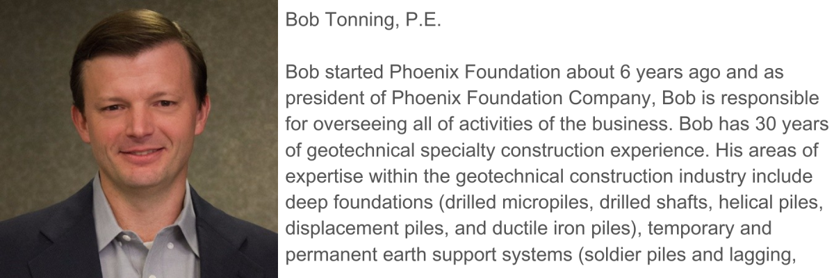
Kurt Amidon, P.E., and Bob Tonning, P.E., Phoenix Foundation Company

Goin' Deep at Fenway: High-Capacity Micropiles Support Air-Rights Project
The proposed “Fenway Center” project will create more than 1,136,000 SF of finished building space within two new high-rise buildings in the heart of Boston. Total construction costs for this project is over $1 Billion. Unlike most construction projects, this development is being built over a 750-foot segment of the Massachusetts Turnpike, an active eight-lane highway traveled by more than 100,000 vehicles each day.
A concrete deck will be constructed over the highway to support these new building. This deck will rest atop three heavily-reinforced and parallel concrete walls, supported by more than 800 high-capacity piles. For most of the center (median) and northern (westbound) walls, driven piles are being utilized to support the high loads. In more congested areas of the site including the entire southern (eastbound) wall located snugly between the Mass Pike and an adjacent railroad corridor, drilled micropiles (“DMPs”) were the most practical deep foundation option.
In addition to a major interstate running through its center, the project site is surrounded by several buildings to the north, two heavily-traveled railroad tracks to the south, and busy public roadways (Beacon Street and Brookline Avenue) to the west and east, respectively. These site constraints limited work zone access for equipment and personnel, minimal on-site storage for materials, and vibration concerns just to name a few. The site’s geology included some of the thickest overburden deposits to be found within the limits of Boston and consist of Fill up to 30 feet thick, over 10 feet of organics, over 20 feet of dense sand & gravels, over up to 190 feet of very soft clays, over a thin layer of hard clay, overlying the Cambridge Argillite Bedrock. Each pile needed to be driven or drilled into Bedrock 200 to 270 feet below existing ground surface.
Phoenix Foundation Company installed 262 DMPs for a total of nearly 12.5 miles comprised by more than 11 miles (over 60 truckloads) of permanent steel drill casing, over 500,000 pounds (10 truckloads) of core reinforcing steel, and well over 2,000,000 pounds of Portland cement.

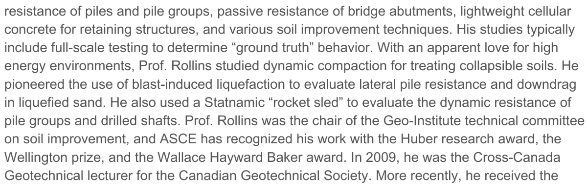

Passive Force-Deflection Behavior of Skewed Bridge Foundations from Large-Scale Tests
Skewed bridges make up 40% of bridges in the US, but have experienced greater distress for both static and seismic conditions for both structural and geotechnical reasons. To investigate their behavior, a series of large-scale passive force-deflection tests were performed on a simulated bridge abutment to evaluate the effect of wingwall geometry and skew angle on passive force behavior. Tests were conducted at abutment skew angles of 0°, 15°, 30°, and 45° with a backwall that was 11 ft wide and 5.5 ft tall. Backfills included sand and sandy gravel compacted to 95% of the modified Proctor maximum density. Wingwalls included concrete walls normal to and parallel to the abutment backwall, as well as Mechanically Stabilized Earth (MSE) wall panels normal to the backwall. Test results indicate that the passive force decreases significantly as the abutment skew angle increases relative to non-skewed walls. There is a 50% reduction in passive resistance when the skew angle reaches 30 degrees. The results also indicate that the reduced passive force can be accounted for using a simple adjustment factor that is a function of skew angle. The skew reduction factor was relatively consistent for all soil types, wingwall styles, and backfill width to height ratios investigated. Displacements required to develop the peak passive force was about 3 to 4% of the wall height regardless of skew angle or soil type. Normalized passive force vs. normalized displacement curves for all tests plotted in a narrow band.
Sheraton Hartford South, 100 Capital Boulevard, Rocky Hill, CT 06067
Discounted Rooms have been reserved on Thursday for this Conference. Here is the room registration link: Book Your Group/Corporate Rate | Marriott International
Early Registration Rates until Sunday, September 1, 2024 extended until September 7, 2024
ASCE Member - Includes NYS PDHs - $275.00 ($325.00 after Sunday, September 1, 2024 September 7, 2024
Non ASCE Member - Includes NYS PDHs - $350.00 ($375.00 Sunday, September 1, 2024 September 7, 2024
Government Employee and Retired People - Includes NYS PDHs - $100.00 ($120.00 after Sunday, September 1, 2024 September 7, 2024
Younger Member - Under 35 Years of Age & Includes NYS PDHs - $175.00 ($200.00 after Sunday, September 1, 2024 September 7, 2024
Student/Faculty Registration - ID Required at Registration - No NYS PDHs - $25.00 ($35.00 after Sunday, September 1, 2024 September 7, 2024
Exhibitor – $800 (Includes 1 Attendee and 1 Exhibit Table, selection of table location first come, first served)
Exhibitor Layout (also at the top of this page)
Exhibitors have long supported our events and can offer solutions for our projects. At our past workshops, seminars and conferences, geotechnical suppliers, contractors, and service providers displayed their latest products for design professionals, contractors, owners, and academicians. We are always looking for exhibitors to join us at our events.
Sponsors have long supported our events and can offer solutions for our projects. At our past workshops, seminars and conferences, geotechnical suppliers, contractors, design engineers, and service providers have sponsored our events to help make them successful and to raise money for CSCE’s Scholarship Fund.
Bedrock Sponsor - 2 Available - $2,500 (SOLD OUT)
This sponsorship level includes prominent display of logo on promotions and program, 1st selection of premier exhibitor booth location (Exhibitor table not included, must register separately), invitation for 2 to the reception dinner the night before, podium mentions, and 2 attendee registration. Please submit your logo to [email protected] after you register for the conference.
Friday Reception Sponsor - 1 Available - $2,000 SOLD OUT
This sponsorship level includes display of logo on promotions, 1 invitation for reception the night before, your company logo on table placards during the reception immediately following the conference, podium mentions, and 1 attendee registration. Please submit your logo to [email protected] after you register for the conference.
Breakfast Sponsor - 1 Available - $1,800 (SOLD OUT)
This sponsorship level includes 1 invitation for reception the night before, your company logo on table placards during breakfast, podium mentions, and 1 attendee registration. Please submit your logo to [email protected] after you register for the conference.
Foundation Sponsor - 3 Available - $1,600 (SOLD OUT)
This sponsorship level includes display of logo on promotions and program, advance selection of exhibitor table location (exhibitor table not included, must register separately), 1 invitation for reception the night before, your company logo on table placards, podium mentions, and 1 attendee registration. Please submit your logo to [email protected] after you register for the conference.
Concrete Sponsor - 5 Available - $1,000 (3 LEFT)
This sponsorship level includes display of logo on promotions and program, 1 invitation for reception the night before, podium mentions, and 1 attendee registration. Please submit your logo to [email protected] after you register for the conference.


